# Elektrische Integration
## Kabel & Biegeradius
{% columns %}
{% column %}
{% endcolumn %}
{% column %}
### Anschlusskabel M16
{% endcolumn %}
{% endcolumns %}
{% columns %}
{% column width="50%" valign="middle" %}
{% endcolumn %}
{% column width="50%" %}
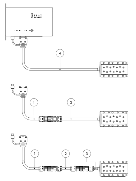
Nur ein einziges Kabel enthält die Leitungen für den Encoder, die drei Motorphasen sowie die Kommunikation mit dem XENAX® Servocontroller.
Gesamtkabellänge max. 20 m
Max. 2 Zwischenkabel (Pos. ②) zulässig.
{% endcolumn %}
{% endcolumns %}
{% columns %}
{% column width="50%" valign="middle" %}
{% endcolumn %}
{% column width="50%" %}
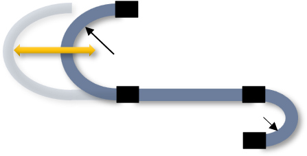
Bei dauerhaft bewegten Leitungen ist ein Mindestbiegeradius von 48mm (Rbewegt) einzuhalten. Das Kabel muss vor und nach dem bewegten Bereich am Außenmantel fixiert werden. Für fest verlegte Leitungen gilt der Einmalbiegeradius von 20mm (Rfest).
Kondition
Mindestbiegeradius [mm]
Rbewegt
48
Rfest
20
{% endcolumn %}
{% endcolumns %}
{% columns %}
{% column width="50%" valign="middle" %}
{% endcolumn %}
{% column width="50%" %}
Das Kabel ist nicht für Torsionsbelastung ausgelegt, erreicht jedoch bei einer Torsion von ±90° über eine Länge von 1 m mehr als 1 Million Zyklen.
{% endcolumn %}
{% endcolumns %}
{% columns %}
{% column width="50%" valign="middle" %}
{% endcolumn %}
{% column width="50%" %}
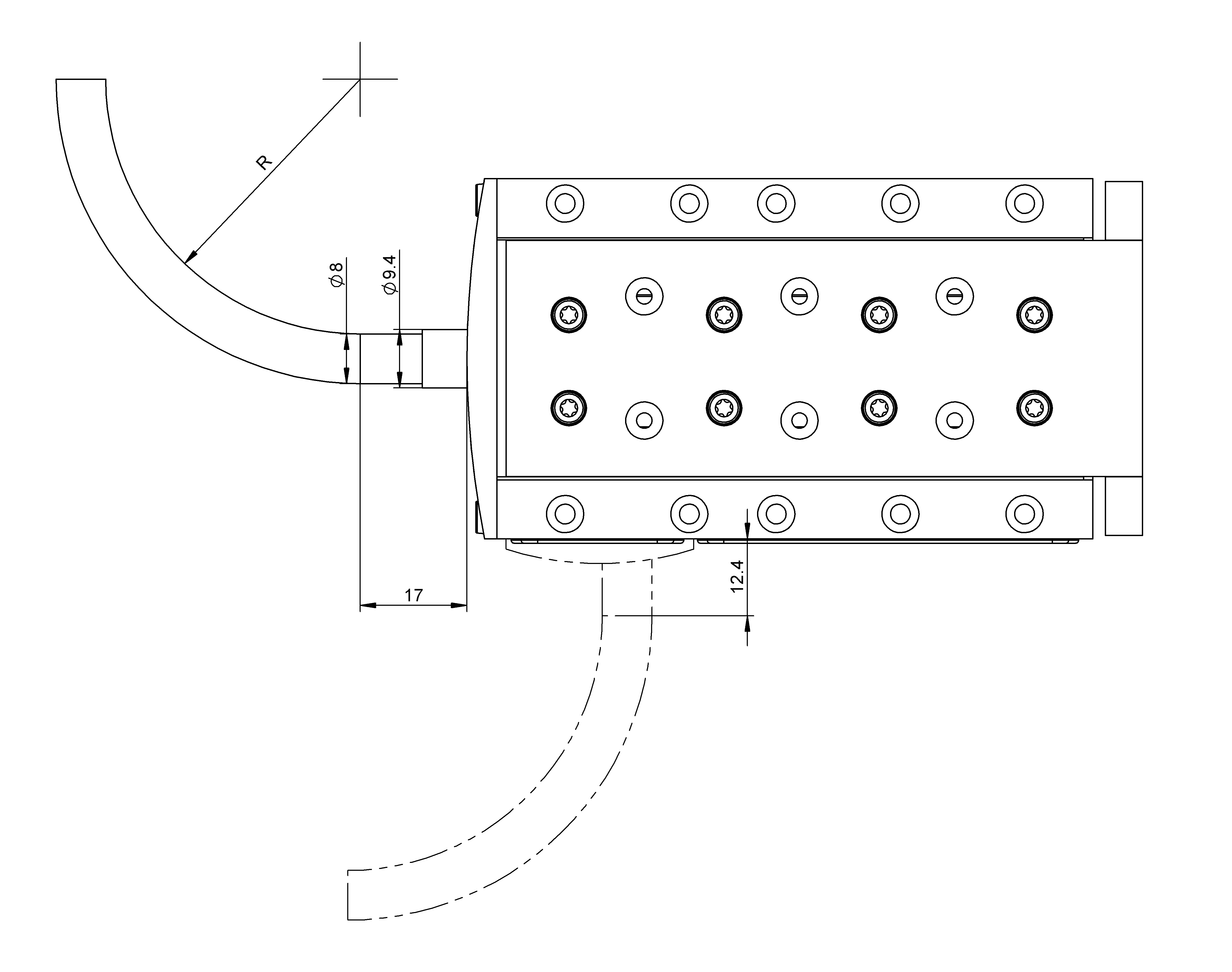
Der Kabelabgang erfolgt standardmässig auf der Rückseite, kann jedoch optional seitlich ausgeführt werden.
Beginnt die Biegung direkt am Kabelaustritt, ist das Kabel zunächst über eine definierte Länge gerade zu führen, bevor eine Biegung oder Bewegung zulässig ist
{% endcolumn %}
{% endcolumns %}
***
## Potentialausgleich
{% columns %}
{% column width="50%" %}
{% endcolumn %}
{% column width="50%" %}
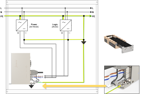
Der 0 Volt Anschluss der Logik Speisung (Pin1) und der 0V Anschluss der Power Speisung (Pin3) muss mit dem GND/Chassis Sternpunkt der Anlage/Schaltschrank verbunden sein.
* Der XENAX® Servocontroller muss auf eine leitende Rückwand geschraubt sein, welche mit GND/Chassis Sternpunkt der Anlage/Schaltschrank verbunden ist. Dabei ist das Motorkabel mit der Schirmklammer zu verbinden.
{% endcolumn %}
{% endcolumns %}
---
# Agent Instructions
This documentation is published with GitBook. GitBook is the documentation platform designed so that both humans and AI agents can read, navigate, and reason over technical content effectively. Learn more at gitbook.com.
## Querying This Documentation
If you need additional information that is not directly available in this page, you can query the documentation dynamically by asking a question.
Perform an HTTP GET request on the current page URL with the `ask` query parameter:
```
GET https://tech.jennyscience.com/motion_systems/motion-systems-de/elax/ex-f20/elektrische-integration.md?ask=
```
The question should be specific, self-contained, and written in natural language.
The response will contain a direct answer to the question and relevant excerpts and sources from the documentation.
Use this mechanism when the answer is not explicitly present in the current page, you need clarification or additional context, or you want to retrieve related documentation sections.